Description
Inertisation
For discontinuous batch processes before process start, the reactor chamber is rendered inert. The inertisation of spaces describes the process to displace the oxygen in the air or other reactive or explosive gases or gas compounds by adding of inert gas.
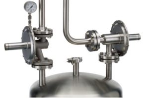
Ventilation/Blanketing
Aim of ventilation/protective gas blanketing is maintaining the inert condition inside the reactor, tank or container during the manufacturing process.

| Reducing Regulator Function | |
 |
Spring-loaded pressure reducing regulators are “relative pressure regulators”, designed to keep the process pressure “B” at a constant level. The nominal pressure is set by means of the setscrew, located at the spring housing. When at rest, the regulator remains in an open position. When the pressure “A” rises, pressure is released through the open valve seat “F” to the process side of the valve and through the internal feedback bore “E” underneath the diaphragm. This will continue, until the diaphragm force “C” exceeds the spring force “D”, while the process pressure “B” rises. The diaphragm is lifted and the vale seat “F” closes. In the event that the process pressure “B” drops below the preadjusted nominal pressure, the spring force “D” presses the diaphragm downwards, so that the valve seat “F” opens and admits gas until pressure equalization is reached again. |
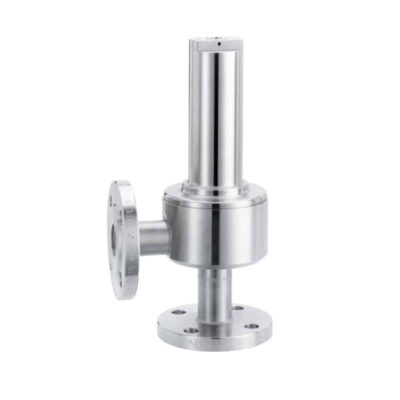
| Relief Valve Function | |
 |
Spring-loaded relief valves are “relative pressure regulators”, designed to keep the process pressure “A” at a constant level. The nominal pressure is set by means of the setscrew, located at the spring housing. When at rest, the regulator remains in a closed position. When the process pressure “A” increases, pressure is released through the internal feedback bore “E” underneath the diaphragm. If the diaphragm force “C” exceeds the spring force “D” the valve seat “F” opens and the over pressure is discharged to the vent side “B”. If the process pressure “A” drops, the diaphragm force “C” is lower compared to the spring force “D” and the valve seat “F” closes. The pressure in the vent line can be atmospheric or vacuum. With vacuum in the vent line the flow capacity of the regulator is increased. |